|
|
|||
| site search by freefind |
(If you don't see the Google Translate's "Select Language", then your browser is blocking google translate...so enable googleapis.com)
Tips for Williams Pinball games
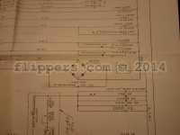
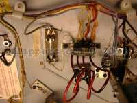
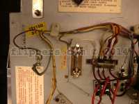
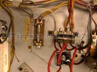
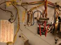
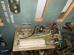
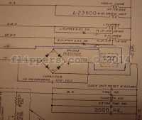
last updated January 25, 2024 Headboard/Backbox Keys (cash doors are all unique for security, no point in tracking them): If others also have the same numbers please contact me (John - jrr@).. Fixing 1971 to 1977 Williams and Recel EM pins with DC coils fuse wiring - when the main solenoid fuse blows and there are no obvious shorted coils? This 10A fuse can be replaced with a 2.5A Slo-Blo fuse, but you should rewire the fuse so that it is on the AC side of the bridge rectifier and not the DC. The reason you want to reqire the fuse is if/when the bridge rectifier shorts out it will blow the main solenoid fuse and you will likely spent a lot of time trying to find the short as it really isn't obvious when a bridge fails. Note that only YUKON SPECIAL had wired the bridge rectifier wired as recommended below AND used a 2A slo-blo fuse, so the modification below is for the following games 1971 through 1977: Williams games this affects include: Recel games this affects include:
A common problem with FIREPOWER and other early WILLIAMS pinball games are failing PROMs, here is the cure;
If you are using a 2732 then: If you are using a 2532 (easier) then:
Subject: TECH: Firepower drop target retrofit

From: estes@MCS.COM (Edward Estes)
Date: 22 May 1995 10:58:50 -0500
Organization: MCSNet Subscriber Account, Chicago's First Public-Access
Internet!
Message-ID: <3pqcbq$9as@venus.mcs.com>
Newsgroups: rec.games.pinball

There has been a bit of traffic lately pertaining to the drop targets
on Firepower, and it prompted me to put together this little info sheet.

I hope someone finds it interesting and/or useful.

Ted Estes
estes@mcs.com


                    Firepower Drop Target Retrofit
                    ------------------------------

The original design for Firepower called for 2 banks of 3 drop targets
instead of the 2 banks of standups in front of the flippers.  The
drop targets were removed at the last moment to save money and because
the drop targets were sure to be a reliability problem in that location,
since they would get heavy abuse.

If you look closely, you may find an early Firepower that had the
wiring for the original drop target banks.  Another clue to the early
age of the game is presence of U-shaped cutouts behind the standup
banks to accommodate "10-point" switches that become accessible after
the drop targets are hit.

(I've been able to dig around in 8 or so Firepowers, and I've only seen
one early one with the cutouts and wire harness for the drop targets.
This doesn't count the actual Firepower prototype which I've had to
pleasure to inspect.)

The software in the game works with either standup targets or drop
targets.  Here is the information on how to put drop targets into your
Firepower.

(I've included wire color information here for completeness.  You get
bonus points if you use the correct colors for your conversion.  The
two games I've converted got their wires -- and drop target banks --
courtesy of a few old Disco Fever games.)

Step 1:  Obtain two 3-bank drop targets.  Any 3-bank sets from a Williams
         game made in the late 70's or early 80's will work (solid state
         game only -- no electromechs).

         Games made prior to Black Knight use a printed circuit board
         and horseshoe wiper switch.  These are notoriously unreliable,
         but are the type originally used in Firepower.  The horseshoe
         wipers are usually bad on an old game, and I've had a hard time
         finding old stock of these to rebuild old drops.  I have ended up
         grabbing parts from a bunch of old drop banks to get 2 working&127;
         banks rebuilt.

         Good old games to part out to get drop targets:  Disco Fever,
         Hot Tip, Phoenix.

Step 2:  Obtain 2 "10-point" leaf switches.
         These can easily be from an old playfield, or wherever.
         Make sure that you get the kind that have the mounting bracket
         extending out from the BACK of the switch.

Step 3:  Remove the old standups.
         Unscrew the switches from the playfield, and carefully desolder
         the wires.  Save the old switches if they are in good condition,
         especially if the decals on them are good.  You never know when
         you might have another Firepower that needs fixing up.  You
         might even want to keep TWO Firepowers -- one with standups and
         one with drop targets -- just so you can do a side-by-side
         playability test.

Step 4:  Make U-shaped cutouts for "10-point" switches.
         Drill/route/cut a cutout behind the two bank locations to
         accommodate the "10-point" switches.  Neatness counts here.
         Make sure you have space to actually mount the switches.
         This area of the playfield is rather cramped.
         Mount the switches after cutting is complete.

Step 5:  Mount drop target banks.&127;
         As noted above, the playfield is a bit cramped.  This is further
         complicated by the fact that the two target banks are angled
         toward each other.  I had to do some cutting of the target bank
         assemblies to get them to fit.  A Dremel tool with a cutting
         wheel works well for this.

         As I recall, I had to cut off one or more of the mounting feet
         on one or more of the drop target assemblies.

         Again, neatness counts.  Be sure to center the targets themselves
         within the oval cutouts and align them nicely.  A sloppy job
         will only bring you the ridicule of your friends as you show
         off your work.

Step 6:  Wire drop target reset coils.
         The backbox wire harness brings the solenoid wires up to the
         connector that mates with the playfield harness.  To do a really
         neat job, find some Molex-type pins to insert into the playfield
         harness connector to bring the signals down to the playfield.
         If you connect directly into the backbox harness, you will not
         be able to remove the backbox when you have to move your Firepower
         through a narrow doorway.

         (I was able to work the pins out of the connector on the above-
         mention Disco Fever harness, and use the whole wire for the
         conversion.)

         Solenoid #2 is the left bank reset (1-3 targets) (Grey-Red wire)

         Solenoid #3 is the right bank reset (4-6 targets) (Grey-Orange wire)

         Wire the drives to the lug of the coils that are connected to
         the anode of the diodes (side WITHOUT the stripe).  Refer to
         another coil on the playfield to double check.

         Connect power to the coils.  Use a Red wire and tack on to a
         nearby coil.  The power goes to the coil lug connected to
         the cathode of the diode (side WITH the stripe).

Step 7:  Wire the switches.
         The drop target switches are wired in the same place in the
         matrix as the standups.  That information is as follows, from
         left to right:

         "1" drop target - switch 17 (Green-Orange/White-Brown)
         "2" drop target - switch 18 (Green-Orange/White-Red)
         "3" drop target - switch 19 (Green-Orange/White-Orange)
         "4" drop target - switch 22 (Green-Orange/White-Green)
         "5" drop target - switch 22 (Green-Orange/White-Blue)
         "6" drop target - switch 23 (Green-Orange/White-Violet)

         The early style drop targets (horseshoe/wiper) had two sets
         of contacts -- momentary and continuous.  The momentary are
         activated while the drop target is on its way down, and the
         continuous are activated while the the target is resting in
         the "down" position.

         The easy way to connect the drop targets is to simply use
         the continuous contacts on each target and connect it as listed
         above.  This is the way later style (Black Knight and later)
         drop targets would be wired.

         The original Firepower, however, used the momentary contacts
         connected as above.  The continuous contacts were connected
         in series within each bank, and connected into another place
         in the matrix.  This gave the software an extra piece of
         information that all the drops in a bank were down.  You
         can connect your drop switches this way, but its extra work
         that is not necessary.  Here are the switch positions:

         "1-3" drop target series - switch 20 (Green-Orange/White-Yellow)
         "4-6" drop target series - switch 24 (Green-Orange/White-Grey)

         The "10-point" switches are wired as follows:

         "1-3" drop target standup - switch 55 (Green-Violet/White-Violet)
         "4-6" drop target standup - switch 52 (Green-Violet/White-Yellow)

         When wiring switches, note that the White wire is connected to
         the anode of the diode (side WITHOUT the stripe), and the Green
         wire is connected to the switch terminal NOT connected to the
         diode.  Refer to another switch on your playfield as a guide.

Step 8:  Double check your work.
         Especially make sure that your coils are wired correctly.&127;
         If you reverse the leads on a coil, you will blow up the
         solenoid driver transistor.  The Red (power) wire goes to the
         coil lug connected to the cathode of the diode (side WITH
         the stripe).

         Check the wiring of the switches.  If switches are incorrectly
         wired, they can mess up other switches in the matrix.

Step 9:  Test your work.
         Run test mode on your game and check out the solenoids and
         switches to verify the correct installation.

Step 10: Play your game.
         Notice that the default "light kickback" rule now makes more
         sense:  The kickback is lit on "1-3" or "4-6" on the same ball
         or spotting the "1-6" lamps.  Now that you have drop targets,
         you can actually keep track of the "1-3" or "4-6" on one ball.

Misc:    The drop target stickers used on Firepower depicted the
         "melting man" as shown elsewhere on the game.  They sport the
         part number 30A-7572.  I have seen these stickers around, so
         they should be obtainable if you look hard enough.  My guess
         is that several rolls of these stickers were printed, in
         anticipation of the production of the game with drop targets.
         Since none were produced that way, that means that there should
         be quite a few stickers floating around somewhere.  (I found a
         few at a local distributor who was kind enough to let me poke
         around on his shelves.  He must have just gone down a list of
         sticker part numbers and ordered a bunch at one point.)
--
Area Lpinball, Msg#14, 17-06-95 19:44:42
   From: John Robertson
     To: All
Subject: TECH: FunHouse ramp problem

* Original Area: Pinball
* Original To  : Uucp (1:153/7080)

To: All

hoid this here...
 JvB> From: d6jvb@dtek.chalmers.se (Johan von Boisman)
 JvB> Date: 17 Jun 1995 08:57:07 GMT

 JvB> My FunHouse is plagued by an annoying problem
 JvB> with the steps ramp. Most balls bounce somehow in the
 JvB> entrance and come back down again. At one side of the
 JvB> entrance to the ramp, a small piece of plastic has
 JvB> been chipped off, but otherwise it *looks* ok.

I have found that most problems with ramps is caused by alignment. It
is very important that the ball is not airbourne on entering the ramp,
and that there is nothing at the entrance that can lift it into the air.
Look for loose metal entrance plate, or the screws aren't tight that secure
the ramp to the playfield. About the broken peice of plastic I recommend
that you cut up a soda pop can and use a section of it to repair the spot
where the break is, you want to reinforce the side walls so that they can
take the impact of the ball striking them, yet they must be firm so the
ball's kenetic energy is not lost in the side wall acting like a shock
absorber. On automatic (solenoid fired) entry ramps the angle the ball
enters is critical to the ball soaring up the ramp reliably. Have fun!
:-#)#
------------------------------------------------------------------------------

Area Lpinball, Msg#55, 16-11-95 22:58:16
   From: John Robertson
     To: All
Subject: Re: Wms tri zone tech help needed&127;

* Original Area: Pinball
* Original To  : Uucp (1:153/7080)

To: All

 a> From: andreas.wennstrom@server1.physiol.umu.se
 a> Date: Thu, 16 Nov 1995 12:54:07 +0100

 a> I have some trouble with a Williams Tri-zone -79...
 a> The whole game is blanked - blanking is low...

I hope you have a logic probe. Check pin 8 of the 556 timer IC23 for pulses,
if no pulses then the timer times out and goes low. The pulses are driven
from PIA 1 and if not present indicate that the CPU is not working properly,
either bad RAM, ROM or something else. Are any of the diagnostic leds on?
Do they blink twice and then go off if you press the diagnostic pushbutton
on the CPU board? If not let us know what led's are on either top or bottom,
blinking or steady....

 a> Does the CPU get any feedback from the driver-board that everything is ok?

No. You can test the cpu with the driver board unplugged and you should get
displays at least.

 a> Can the CPU hold the blanking output low if there is
 a> something wrong with the driver-board?

Yes, if a PIA is shorted then you could get external cause for blanking to be
low, unplug driver board and check blanking.

 a> Are there other Wms-games that shares the same CPU-board and system?

Well, yes most games from that period use a similar cpu/driver setup, all the
way from FLash through Stellar Wars  at least, including Black Night,
Barracora, Disco Fever, all use the same blanking setup and base driver board
wiring, although the CPU changes around the principle remains the same.

 a> Does anybody know how to use the eight DIP-switches
 a> 'MASTER COMMAND' (Together with 'Command Enter
 a> button??)??

MAster Commmand is the CPU diagnostic switch, Tri Zone does not, I think,
still accept programming information from the DIP-switches, data is entered
from the coin door's Advance/Auto-Up/Manual-Down switch bank.

 a> Is it possible to test the CPU-board with the Driver board disconnected?

Yup, although I have found that some CPU's won't work with the driver
unplugged, the theory, and manual suggests that the CPU will work without
the driver. I suspect that the games that don't work are multi-ball(tm) and
thus are looking for the switch closures to set up, any other suggestions??
Jonathon, feel free to comment here.....

 a> And what is 'memory protect'?

This is a way of allowing the operator to change the programmable operation
of the game, when the Coin door is open it allows data to be written to the
CMOS ram's game adjustment area, hen the Coin Door is closed, only the
bookkeeping data from the game can be changed, ie: # of coins, high scores,
# of balls won, etc.

 a> Thanks!

You're welcome!
------------------------------------------------------------------------------

Area Lpinball, Msg#62, 26-11-95 22:23:36
   From: John Robertson
     To: All
Subject: Fixing up a TZ -- in exhaustive detail ...

* Original Area: Pinball
* Original From: Jonathan N. Deitch (1:153/7080)
* Original To  : All (1:153/7080)

From: musjndx@gsusgi2.gsu.edu (Jonathan N. Deitch)
Date: 25 Nov 1995 00:29:22 -0500
Organization: Georgia State University
Message-ID: <4969ji$3or@gsusgi2.gsu.edu>
Newsgroups: rec.games.pinball

Well, I've been thinking on this for a long time ... TZ owners, here's
your "fix-it" bible ...

First a disclaimer -- I will *not* take responsibility for ANY damage
done to your machine by anything I describe.  What I describe are things
I have found work for me.  They may not work for you.  If you do not feel
comfortable doing any fix or repair needed for your game, DON'T DO IT !

It's usually cheaper to hire someone to do it right than to hire someone
to *undo* what you've done wrong and *then* do it right.

Also, the latest version of this document (I've changed a few things
and this is actually a *repost*) is at :

http://www.gsu.edu/~musjndx/tz-fixit.html


So now that you're scared to death to lift that screwdriver ... :-)

Twilight Zone is one of the most complicated pinballs Williams/Bally has
ever produced ... it's the only game that I know of that (in its prototype
form) used all the coil drivers, the entire lamp matrix, the entire switch
matrix, all eight switches on an auxillary "9th" switch column, and an
entire 8-driver auxillarly coil driver board ... plus all four flipper
positions on the flipper board !

Twilight Zone has several major subassemblies :


The Clock
=========
TZ's clock is a wonderfully designed piece of mechanical engineering that
can actually tell *real* time, if that option is enabled in the software.

Unfortunately, it has an achilles heel that can bring the whole mechanism
to a screeching halt -- heat !

See, the Clock was originally designed so the lamps were on the game's
lamp matrix ... for what reason I'm not sure, but probably to do some
neato strobing effects ... anyways, the designers ran out of available
lamp slots on the lamp matrix and the clock lamps were moved to the
GI circuits (same circuit as the "Twilight Zone" in the backbox, BTW) ...

When this was done, the diodes needed for the lamp matrix were replaced with
jumpers as they aren't needed for GI lamps.

Unfortunately, the result is light bulbs that get VERY hot from the
GI circuit as they're on *all the time* ... and this heat will almost
certainly destroy the optos in the upper parts of the clock as there is
no ventilation for the heat to escape through !  What's more, the pins that
connect the minutes opto board to the hours opto board get cooked by this
heat as well and delaminate, causing a very poor connection between the
two boards and spurious problems with the hours optos ...

The solution to this problem is to first replace the jumpers installed in
place of the lamp matrix diodes (D1-D4 on the minutes opto board) with those
diodes again.  1N4001 or 1N4004 diodes work fine.  Direction doesn't matter
as GI power is AC, but the PCB is actually silkscreened for the original
diodes.

Second, you need to remove the clock guts from the clock casing and drill
ventilation holes in the clock casing.  I usually put two in the back part of
the roof for the back part of the clock (so the hours optos can stay cool) and
two in the front part of the roof right over the light bulbs (between the
PCB and the clock face) so the light bulbs' heat can escape.  I also drill
inlet vents on the lower parts of the sides in each section so cool air
can come in.  Natural convection will take over to cool the clock as the hot
air rises, escapes, and cool air is drawn in to replace it.

You will also need to replace the pins between the PCB's if they are
visibly cooked (they'll look tarnished) and any optos that have been damaged
by the heat.

When you reassemble the clock, pay close attention to the instructions in
the manual -- it has very specific steps to follow for proper clock alignment.


The Gumball Machine
===================
The Gumball Machine is, if possible, a cooler piece of engineering than the
clock.  It's main point of failure is dirt.  There is only one switch inside,
called "Geneva" that is used to detect one revolution of the mechanism.  If
this switch gets too dirty, it can fail to make contact when closed causing
a failure.  Other points of failure are on the opto pair at the entrance
to the Gumball (on the wire rail) ... Kevin and Keith once reported theirs
*broke off* the wire rail ... anyways, these are subject to quite a bit
of vibration and this can cause broken LED legs and failure.  Lastly, the
gumball popper, like all ball poppers, is subject to dirt that can occlude
the opto's lens ... this will cause the game to think a ball is permanently
in the popper ...


The Bridge Diverter
===================
This is the thingy on the Right Ramp that 1) drops the ball into the
left spiral for you to bang into the Piano or 2) hurredly gets out of
the way on a Powerfield shot ...

It is connected via a pull wire directly to its coil, so if it doesn't
go down, it's usually due to a broken wire, a bad coil, or something
hanging the mechanism up ... assuming, of course, that the opto on the
right ramp is functional ...

What is *more* common, however, are two problems :

1) The ball bounces into and out of the carriage, and rolls waaaaaay back
   to the right.  The Diverter diverts and slams the ball (which is now back
   to where it's supposed to be) SDTM when it pops back up.  This is fixed by
   adjusting the height of the middle of the wire rail -- the leg that mounts
   onto the left post of the left ramp entrace is supposed to be firmly
screwed
   into place.  It may need a washer or two underneath it to shim it slightly
   upwards.

2) The other major problem is it dumping the ball either out the side or up
   the spiral loop ... this can be fixed with some *very* gentle bending of
   the carriage ball guides to help the ball along the proper trajectory.

Lastly, the hinge pin (part # 02-4837) can get *very* worn over time,
causing a MAJOR wobble in the diverter carriage.  This can cause both problems
#1 and #2.


The Powerfield
==============
Most of the powerfield problems are electrical in nature, especially with
the magnets.  The biggest thing to watch out for here is that two plugs
on the wiring harness are IDENTICAL.  One goes to the optos, the other
to the magnets and flashlamps.  Needless to say, plugging them up backwards
will put a 50vdc potential to your opto detectors and fry them but good.

Double check *carefully* before plugging this sucker back in ...


Flippers
========
TZ's flippers are as followings :

Lower left/right : FL-15411 coils
Upper left : FL-11753
Upper right : FL-11722

I strongly suggest an outright replacement of : coil stops, coil sleeves,
crank/link assemblies, and the coil itself if the sleeve won't slide in and
out easily.  The parts are inexpensive and replacing 'em is much easier than
trying to resurrect worn parts.  Worn parts have fairly obvious flat spots
and/or mushrooming on the ends.  You will also want to replace the return
spring if needed ...

Parts needed : Coil Stop (A-12111), Crank/Link (B-13882-R or L), Coil
               Sleeve (03-7066-5), and if needed the return spring (10-364).

One other thing to watch out for the the EOS paw on the crank -- this is the
little arm that strikes the EOS switch blade.  Normally there's a piece of
1/4" heat shrink tubing here to prevent metal from rubbing on metal, but on
older flippers it has often rubbed off -- and the steel of the crank will
cut right through the copper of the EOS switch.  So if you find your old
crank has worn through the heat shrink tubing, consider replacing the EOS
switch as well -- part # SW-1A-194.

I align flippers so the facing of the rubber (speaking of which, TZ shipped
with *red* rubber ... the part # in the manual is for *red* rubber, but
the name given is for *yellow* rubber) is perfectly parallel with the
wall that feeds the flipper ... either the wall of the upper loops or
the wall of the return lanes.  This may or may not work for you.


Under-playfield Mechanicals
===========================
Be on the lookout for three problems (other than the Piano and Camera landing
areas coming loose) :

1) The left wall of the Slot kickout loop can break loose.  This usually
   happens on games with no bracing on the Slot Greed target.  This requires
   replacement of the loop unless you can spot-weld the wall back in place.
   If this isn't fixed, balls will not kickout reliably and can kick out
   straight down the middle !  I brace replacement loops with a screw fastened
   across the middle, just back from the kickout edge.  If it is located high
   enough (ie: just under the mounting flanges) the ball will fly right under-
   neath when it is kicked.

2) Speaking of the Slot Greed Target, this beast is not normally supposed
   to collapse backwards ... instead it's supposed to send balls that hit
   it straight down the middle !  It can be braced from the rear by installing
   a slingshot hinge so the long part of the L sticks out behind the target's
   backrest and the two screw holes on the short part of the L are between the
   base of the slot greed target and the lower target on the side bank.  It
   fits right into place there between the two target bases.

3) Lastly, like the kicker in the bottom of Thing's box, some Slot machine
   kickers have a tendency to crack right off the base of their mounting
   brackets ... if you see cracks forming, order a new one ASAP !


ERRATA
======

- Have you found your "Upper Right Flipper" flashlamp yet ?

  Hint : Look *under* the plastic above the UR flipper ...

- If you are plagued by airballs that hit the righthand Powerfield sign,
  make sure your flipper rubber is *above* the bottom line on the flipper
  paddles and that your Slot Greed target is properly supported.  Otherwise
  you are just inviting balls to mimick F-16's ...

- Check your Auto-launcher and Rocket kicker -- they are supposed to have
  special kicker arms with *cupped* kickers to help aiming ...

- If you have a White clock game and the post for the third magnet, check
  your wiring harness -- likely all the wiring is there for you to reinstall
  the third magnet and its opto plus the clock passage opto *and* the
  second Autoplunger opto!  You get no real benefit from doing so, but it's
  kinda neat to own a "retro" TZ ...

  The game will recognize and use the third spiral magnet in "Spiral" mode,
  but it ignores (completely) the clock passage opto.  I'm not sure if it
  does or doesn't use the second Autoplunger opto, but I've seen ours put
  two balls in there ... whether due to trough switch problems (which I
  just fixed) or that opto is unknown.

- Have you seen the roadmap under the Right Ramp yet ?  If not, you need to
  clean your ramp ... :-)


That's all I can think of for now ... I'm sure I'm gonna get plenty of
corrections (I typed all this in off the top of my head) ...

- Jonathan

"Braves Win !  Braves Win !  Braves Win !  Braves Win !" -- Skip Caray (1992)
                    We are NOT "Loserville" anymore !!!
--
musjndx@gsusgi2.gsu.edu     | "I Hate it when I can't trust  | Atlanta 1996 !!
jdeitch@aol.com             |  my own technology!" - LaForge | Play Pinball !!
http://www.gsu.edu/~musjndx |-------------------------------------------------
---------------------------- "Thrills!  Chills!  Magic!  Prizes!" -- Hurricane

Roddenberry, Asimov, Henson, Dr. Seuss, Mel Blanc, Friz Freleng ...  Sigh ...
------------------------------------------------------------------------------

Area Lpinball, Msg#113, 23-02-96 12:18:44
   From: John Robertson
     To: All
Subject: Re: TECH: TZ miscellany

* Original Area: Pinball
* Original To  : Uucp (1:153/7080)

To: All

More roadkill on the ......

 AJ> From: afljoeys@aol.com (AFL JoeyS)
 AJ> Date: 23 Feb 1996 02:07:27 -0500

 AJ> However, inevitably, I've got a few more questions/problems... these,
 AJ> fortunately, are somewhat less critical.

 AJ> 1) The realtime clock loses time when the game is turned off.  What's
 AJ> interesting is that when powering up the machine again, the time it shows
 AJ> is neither some default time (as one might expect if the RAM got reset),
 AJ> nor the time when it was powered down... instead it's some time between
 AJ> when the machine was powered down, and the correct
 AJ> time -- as if the clock
 AJ> was running slowly while turned off.  All other saved parameters (high
 AJ> scores, configuration settings, etc) are stored correctly while the
 AJ> machine is off.  Any idea what might be causing this?

First, check the battery voltage - should be 4.1 or higher VDC, then check it
at the real-time-clock chip toi make sure it is getting proper power. If this
OK, then replace teh clock's crystal (tiny cylinder with two wires if I remem-
ber correctly on that model). Try leaving the game on overnight and see if it
looses time, if not then probably power related if so then probably the
crystal!

 AJ> 2) On occasion, a ball shot up the Hitchhiker lane
 AJ> (either by Rocket or by
 AJ> flipper) gets stuck under the Powerfield.  I'm told this is somewhat
 AJ> common on TZ's.  I'm assuming that the cardboard? underside of the
 AJ> Powerfield sags a little, catching the ball.  The
 AJ> question: is this indeed
 AJ> common?  If so, is there any recommended method for fixing the problem?

This is caused by the plastic flap on the light shield (that comes down from
the Gumball machine area) sagging down a bit. Remove Mini-playfield. Cut a
small peice of sheet metal about 1" (2.54cm) by 4" (10.16cm), then bend one
end 90 degrees and slide under the light shield and on top of the two metal
ball loops, secure to something and replace the mini-playfield. Took a little
while to catch this as the ball never stuck when I played, only when
customers did!

 AJ> 3) My extra ball buy-in button is malfunctioning.  Specifically, Switch
 AJ> Edges shows that pressing that button does NOT trigger the Buy-in switch
 AJ> (23), but instead triggers (both) Right Ramp (73) and Left Magnet (83),
 AJ> which are coincidentally (ha) on the same row as the buy-in button.  I'm
 AJ> assuming that this is a switch matrix problem, but since I've never had
 AJ> one of those before, I'm not sure how to track it down.  Suggestions?

Put game into switch test and check ALL switches on both the ROW and the
COLUMN that share these numbers - 73, 83, 23, I think you will find that
all switches on the X3 line will show when any switch there is closed.
Check it's driver transistor - will be shorted - usually caused by static
electric shock, please ground yourself to the frame of the glass BEFORE
touching and wires or connections inside the game, Make sure the game is
plugged in and turned off before opening the cabinet to protect from&127;
static electricity, and there MUST be a ground pin in the power cord and it
MUST connect to a GROUNDED outlet, both for safety and for static elctric
protection!!!

 AJ> 4) What is the "normal" accuracy of the Rocket?
 AJ> (Where an "accurate" shot
 AJ> would be one that goes around the Hitchhiker lane and into the pop
 AJ> bumpers)  My Rocket makes an accurate shot approx. 85% of the time... is
 AJ> this reasonable?  If not, how might it be improved?  (The machine is
 AJ> properly balanced -- ~6.5 degrees slope, and left/right balanced,
 AJ> according to a level.... although it IS on carpet, so it's subject to
 AJ> slight variation.)

Rocket should send ball straight up Hitchhiker lane 10/10 shots, make small
bends in the kicker arm to correct or slight bends in the guide metal.
Ah-HAH - "although it IS on carpet" AGAIN, MAKE SURE THAT THE GAME IS
GROUNDED TO PROTECT FROM STATIC ELECTRICITY!!! IF YOU CAN MAKE A SPARK
YOU
CAN DAMAGED THE MACHINE!!! (sorry about yelling)

 AJ> That's all for now.  Thanks in advance for any and all assistance!

's alright.

:-#)>
------------------------------------------------------------------------------

Area Lpinball, Msg#118, 11-03-96 23:04:28
   From: John Robertson
     To: All
Subject: Ask Uncle Willy; March 11, 1996

* Original Area: Pinball
* Original From: Ted Estes (1:153/7080)
* Original To  : All (1:153/7080)

From: estes@MCS.COM (Ted Estes)
Date: 11 Mar 1996 17:07:28 -0600
Organization: MCSNet Services
Message-ID: <4i2bng$dnb@mars.mcs.com>
Newsgroups: rec.games.pinball

Here is a special installment of Ask Uncle Willy, where Uncle Willy tries to
shed some light on buying a pinball for home use.  Uncle Willy's mailbox has
been overflowing with inquiries about buying games, and how to fix them.

Uncle Willy answers your questions about pinball machines.  The questions
should be of a general-interest nature, and will be answered via an article
posted in rec.games.pinball, and subsequently archived at:

        http://www.wms.com/williams/willyworld.html

Asking questions of a proprietary nature ("How many of game X were produced?"
"What games do you have in the works for this fall?"  "What game is designer
Y working on?") will not get you very far, as Uncle Willy is constrained from
answering them.

Mail your questions for Uncle Willy to:

        uncle_willy@wms.com

Question:
    Can I buy games directly from Williams Electronics Games, Inc.?

Answer:
    Williams Electronics does not sell directly to end customers.  Much like
    an automobile company, Williams has a network of distributors throughout
    the world.  Your first stop in buying a new pinball or video game should
    be at your local distributor.  Likewise, if you are looking for parts for
    your pinball or video game, your distributor is the place to start look-
    ing.

Question:
    I want to buy an older pinball/video game.  Does Williams have Defenders
    and Firepowers in stock?

Answer:
    Williams Electronics is in the business of producing new arcade equipment.
    Games are produced to order, and shipped to distributors as they come off
    the assembly line.  Just like you wouldn't expect to go to your local
    Ford dealer and be able to buy a 1965 Mustang brand new, you would not be
    able to buy an older arcade game brand new.

Question:
    OK, then, where DO I go to find that classic arcade game?

Answer:
    This question has many answers, depending upon how much time you want to
    put into tracking down a particular game, how much work you want to put
    into making your game playable, and how much money you want to spend.

    The easiest way to buy a pinball or video game for home use is to go to
    a business that specializes in the sale of games to the home.  Look in
    the Yellow Pages under "Amusement Devices - Home", or some similar head-
    ing.  Also, the local advertising newspaper usually will have several
    such businesses advertising items for your game room.  Visit more than
    one such business, if possible, and take time to talk with the proprietors
    about what you are looking for.  If you have your heart set on a parti-
    cular game, it is usually possible to ask them to locate one for you.

    Don't expect a bargain from a home game room store.  The prices there tend
    to be high.  However, you must keep in mind what you are paying for.  The
    game you buy should be completely refurbished and working correctly.  The
    price should include delivery, setup, and some sort of warranty.  You will
    probably also get a handful of spare parts, such as pinball rubbers, lamps
    and fuses.  You also now have someone to call, should you have a problem
    with your game.  You can expect the store to have the parts on hand to
    fix the more common problems that might arise with your game.  You should
    also get the manual and schematics for your game.

    Another good place to check for used games is your local arcade distrib-
    utor.  Often, they will take games on trade-in from operators buying
    new games.  Some distributors will even cater to home sales, providing the
    sort of service that you can get from a game room store, although you
    should keep in mind that the distributor's main customer is the arcade
    owner or operator.

    If you are seriously thinking about diving into the hobby, and want to
    save money by fixing up your own games, you have many avenues from which
    to track down games.  This takes a lot of time and footwork, and Uncle
    Willy would refer you to the Pinball Archives, where you can find some
    excellent information on obtaining and restoring pinball machines.  The
    Pinball Archive is at:  http://www.pinball.org/  You should be sure to
    visit the information page there:  http://www.pinball.org/Info   The
    newsgroup rec.games.pinball is another place to look for information, and
    to ask questions.

    For information on video game collecting, you should check out the news-
    group rec.games.video.arcade.collecting.  You can find the FAQ for that
    group at http://www.monefieore.ulg.ac.be/~vecoven/rgvac/rgvacFAQ.html

Question:
    Alright, now I have that classic pinball/video game I've always wanted,
    and I'm trying to fix it up.  Where do I get parts?

Answer:
    For game non-specific parts, you should check out the vendors listed in
    the Pinball Archive.  This is usually your best bet for pinball rubber,
    lamps, coils, flipper links and similar items.

    If the game in question is of recent manufacture (say five years or so),
    the best place to look is at your distributor.  They will either have
    parts in stock, or can order them for you.

    For an older game, you will have to look at secondary sources.  You should
    check out some of the resources listed at the Pinball Archive.  There are
    many businesses that cater to the pinball and video enthusiast.  Also,
    you should subscribe to a magazine, such as Game Room or pinGame Journal,
    to scan the classified ads for items for sale.  (Again, visit the Pinball
    Archive for the addresses to those magazines.)

Question:
    How do I find a manual for my pinball/video game?

Answer:
    At the risk of sounding like a broken record, the answer again depends
    upon the age of the game.  For a newer game, your local distributor is the
    best bet for purchasing a manual and schematics.  Otherwise, check out
    the Pinball Archive and the above-mentioned magazines for sources.

Question:
    OK, I figure I can tackle the mechanical restoration of my new pinball,
    but right now it doesn't function.  When I turn it on, the lights come on,
    but I don't see anything in the displays, and I can't start a game.  What
    could be wrong?

Answer:
    Anyone who has helped people with repairing pinball games will have read
    the above question with a wry smile.  On many pinball games, the general
    illumination ("GI") lamps will light regardless of the condition of the
    "brains" of the pinball machine.  In fact, most of the circuit boards can
    be removed, and the GI will still light up.  If you look closely at a game
    in the above-mention condition, you will notice that none of the
    controlled lamps (Extra Ball, Bonus X, etc.) will be functioning.  This is
    because something is keeping the CPU board (the "brains") from functioning
    correctly.

    Repairing the circuit boards in a pinball machine is an undertaking only
    for the qualified technician.  If you have not repaired electronic&127;
    circuitry before you should seek out a repair service.  You may want to
    call your distributor for electronic service help.  They will have the
    equipment to repair newer pinball games, and many distributors welcome
    repairs on older pinball electronics as well.  Otherwise, your distributor
    may be able to refer you to someone in your area who caters to the home
    market.

    Several pinball repair services are listed in the Pinball Archive FAQ.
    Additionally, you may want to check out the services advertising in Game
    Room magazine and the pinGame Journal.  Most repair services will fix
    circuit boards by mail, but you should be comfortable removing and rein-
    stalling the boards before attempting this.

    Also, you should be aware that a problem in the electronics of a pinball
    many times will cause some other problem in the game, such as a     burnt
    coil or display.  (Sometimes, a problem in the pinball, such as an
    electrical short, will be responsible for the electronics failure.)
    Therefore, just getting your electronics fixed will not always be the end
    of your repair.  You don't want to put that newly-fixed circuit board back
    into a machine just to watch it be damaged again.

Question:
    Well, my pinball machine is working fine, except for feature X.  What
    could be wrong?

Answer:
    Uncle Willy is sorry, but it is outside the scope of this column to help
    diagnose problems with your pinball machine.  For newer games, you will
    want to give your local distributor a call.  For a game-specific problem
    on a newer game, you may want to send email to the appropriate electronic
    mail address; see the email contacts at http://www.wms.com

    For older games, check those repair service resources mentioned above, or
    post a question on rec.games.pinball or rec.games.video.collecting.

Question:
    My uncle has this old pinball machine in his basement; what is it worth?
    I saw an Addams Family pinball for sale at X dollars; is this a good
    price?

Answer:
    Pricing a used pinball machine is not a cut-and-dried exercise.  A recent
    used title has value based upon its earning potential.  An older piece is
    mainly valued by its collector value.  Those in between tend to be
    influenced in price by the home game room market.  (Many people buying for
    a home game room want something that looks nice, or fits into their decor
    rather than a particular title.)

    A used pinball machine, just like anything else, is worth what someone
    will pay for it.  Many factors affect this: popularity, availability,
    condition.  While many games can be restored in functionality, cosmetic
    flaws, such as a worn playfield or a flaking backglass, will adversely
    affect the value of a game.  A game in good cosmetic condition, but need-
    ing major mechanical repairs has a reduced value, do to the amount of
    time, effort and materials needed to bring it up to standards of desir-
    ability.

    A pinball of older vintage doesn't necessarily imply that it is of
    greater worth.  Older games don't have the excitement level of newer
    games.  Even with the nostalgia factor, the pool of serious collectors is
    relatively small, and everyone has different interests.  Since pinball
    machines require significant floorspace, amassing a sizable collection of
    games is not a possibility for most people.

    Also keep in mind that one person's trash is another one's treasure.
    Uncle Willy has seen friends pay good money for stuff that Uncle Willy
    wouldn't haul home for free to use as firewood.  On the flipside, however,
    Uncle Willy himself has been known to pay a premium for a pinball game
    that he just had to have that was in particularly nice condition, and on
    which the restoration work had already been done.
It all hinges on one tiny capacitor - C9 - located just to the right of the LM323 5VDC regulator. The schematic calls for this to be a 0.39ufd and that it is supposed to be connected to the supply side of the LM323, however the PCB trace layout connected it to the OUTPUT side of the LM323 - making it pretty much useless against dealing with dropout filtering...as we all find from time to time. So the simple cure is to add one 1.0 ufd Tantalum Capacitors to the board - across the input to ground, and a second (can't hurt and meets design specs) across the output and common.
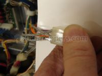
Still having trouble? Loud or irritating SPEAKER HUM? Remove pin 12 of 3P1 (large rectangular MOLEX plug to Regulator board that leads to the transformer), and simply solder the crimp connection. Solder ALL the other pins while you are there for reliability...
Hi XXXX! Sorry, but due to lack of time I can not help folks technical questions in private email. Please post your questions to the newsgroups rec.games.pinball for the (eg..)Gottlieb problem, and rec.games.video.arcade.collecting for the (eg..)Space Duel problem. Do the search in http://www.googlegroups.com for both games (eg.. for the Gottlieb problem do a search for "Gottlieb" "Tech" "System I" or "System 80") and you should find most of your questions answered... Try the historical archive there as well, a LOT of repairs tips are there. You shall probably find that I or others will help in the newsgroups as that is a public forum and we like to help as many as possible... John :-#)# Sparky wrote: If you have a replacement tube you can carefully (!!) press the legs of the new tube up against (game TURNED OFF) the unknown condition tube and see if it lights up when someone else turns the power on, and then off. If the new tube lights up at all then the suspect tube is dead. If the new tube does not light up, check your setup, try again, and if still dead test the new tube against the known-to-be-working player (4 in this case). If the new tube does work then you need to replace the driver IC for player 3 (in this case). DO NOT ATTEMPT THIS ON YOUR OWN - unless you like replacing ICs that blow because you move the display under test while trying to turn the game on/off. John :-#)# Bram Stocker's DRACULA - MIST Multiball problems... Once I realized this it was easy to fix - simply add a 50K small potentiometer (pot) in series with the 100K resistor (R4 on the Opto-12 board) then adjust the pot to its center position and try again. If OK, then leave it alone, if not then increase the resistance slightly (1/8 turn) and test again. Small resistance changes lead to large Detector Threshold changes... "The game is operating but twice on bootup the display has shown "IRQ Then if I turn off and on the game boots into ready mode, and plays perfectly. It has been blowing the 2.5a fuses F2A and F4 on the Aux power board, So far I have checked the main mpu pcb, the aux power pcb, the main Williams System 11C Sound Boards - D-11581-XXX(XX) System-11C Sound Circuitry Tests
|
(jrr-at-flippers-dot-com for those who do not have their browser set to open their email client) |
 Click here to order Parts