BALLY HOME PINBALL UPGRADES & TIPS
Updated
April 15, 2024
A few ideas on how to possibly fix your Bally Home pinball game, and tips to keep it running for years to come.
One thing to watch out for is that the transistors with the metal tabs must NOT by lying down flat on the board, particularly if there are traces underneath them. Best to carefully bend them to a 45 to 90 degree angle if they are too close to the logic board. If they are not close, then don't bend them as each time the leads are bent the closer the transistor legs are to breaking...
Menu:
Series I
Series II
Troubleshooting
Repair LEDs
SERIES I
606-1000 FIREBALL
614-1000 EVEL KNIEVEL
614-3000 FIREBALL (might say 614-0300 FIREBALL on some games)
Expected voltages:

Power and RESET:
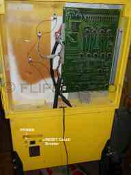
1) Common problems: game is unresponsive to self test, or it acting erratically. First thing to do is to replace the 22uf 25 to 35VDC capacitors on the main computer board (MPU) - there are three of these on the 1st generation MPU: labelled 5VDC, 12VDC, and 6VDC in the "Expected Voltages" photo above. Try the game again - this may solve your problems, but in any case is recommended as the capacitors are getting too old to be reliable.
2) Check that the voltages are close to those indicated on the image above, check with your leads across the capacitor, positive lead on the top negative to the bottom lead of the capacitor. If voltages are off then you need to check the regulator board under the playfield at the rear of the game body. Photos show 5VDC, 12VDC, and LED (6ish VDC) test across the MPU capacitors. If no voltage or lower than shown you have a power problem to sort out!
  
Check for good 18VDC and 20VDC - use the ground at the bottom of the left two capacitors as above:
 
3) Power supply (Series I):
A common problem for Bally home pinball games is to have overheated connections on the power supply as well as failure of the 18VDC regulator - which powers the +12VDC for the Series I MPU (above).
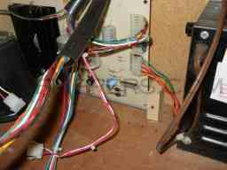
We sell a fuse upgrade kit for these System 1 games to help protect against damage to coils or other components if anything goes wrong with the power supply or computer.
4) Problems with switches on the playfield? This can be caused by cracked solder traces where the Molex female connector plugs on the right angle Molex header pins on thecircuit board that the switches and lights are mounted on. It is a good idea to resolder the pins on the headers to reduce intermittent or unresponsive switches or lights. If there are still problems with switches or lights then run the troubleshooting precedure in the repair manual. Copies available here...
SERIES II
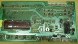
614-2000 GAPTAIN FANTASTIC
614-4000 GALAXY RANGER
614-5000 FIRE BALL
1) Common problems: game is unresponsive to self test, or it acting erratically. First thing to do is to replace the 22uf 25 to 35VDC capacitors on the main computer board (MPU) - two capacitors of these values are on the 2nd generation MPU. Try the game again - this may solve your problems, but in any case is recommended as the capacitors are getting too old to be reliable.
2) Check that the voltages are close to those indicated on the image above, check with your leads across the capacitor, positive lead on the top negative to the bottom lead of the capacitor. If voltages are off then you need to check the regulator board under the playfield at the rear of the game body.
3) Power supply (Series II):
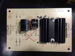 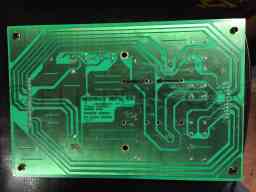
A common problem with the Home series of games are failing capacitors leading to bad +5VDC for the Series II MPU (above).
4) Problems with switches on the playfield? This can be caused by cracked solder traces where the Molex female connector plugs on the right angle Molex header pins on thecircuit board that the switches and lights are mounted on. It is a good idea to resolder the pins on the headers to reduce intermittent or unresponsive switches or lights. If there are still problems with switches or lights then run the troubleshooting precedure in the repair manual. Copies available here...
TROUBLESHOOTING:
Series I & II
Problem: Game does not advance to next ball (and player if more than one player) when the ball drains to the outhole and is ejected back to the shooter trough.
Possible Cause: The ball switch A/B/C/D did not register that the ball entered the playfield. If none of those switches operates when the ball enters the main playfield, then the computer does not advance the ball/player count when the ball drains.
Test: Put the game into play mode with the glass off and check each switch manually to ensure each switch makes a scoring sound and turns OFF the lamp just above it. I recommend that you roll the ball over the switch to make sure it will be tripped by the ball...
Coil Driver Transistor Locations by Series
| Coil |
Series I |
Series II |
| Ball Ejector |
Q236 - TIP145 |
S2 - TIP145 |
| Left Sling Shot |
Q234 - TIP145 |
S3 - TIP145 |
| Right Sling Shot |
Q232 - TIP145 |
S4 - TIP145 |
| Left Thumper Bumper |
Q230 - TIP145 |
S5 - TIP145 |
| Right Thumper Bumper |
Q228 - TIP145 |
S6 - TIP145 |
If you have to replace a driver transistor then we recommend that you replace the diode on the coil it controls. chances are the diode has failed, and they are quite cheap. Use a 1N4004, 1N4005, 1N4006 or 1N4007 diode and be sure that it is installed with the band to the same coil lug as the previous diode. The WHITE wire MUST connect to the coil diode banded sidelug. The WHITE wire is the DC power for the coils, it must never go anywhere but to the coil and the band side of the coil diode!
Note that TIP145 can be replaced by: TIP146, TIP147, 2N6042, or SE9400. Or any transistor of similar gain and current cpacity.
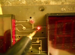
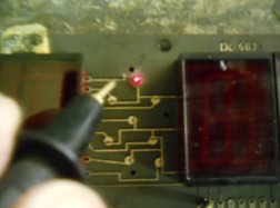
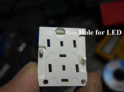
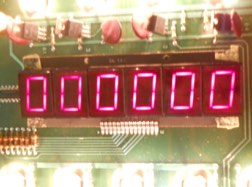
LED DISPLAY REPAIR
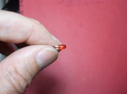
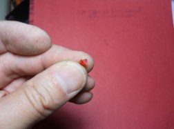
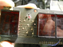
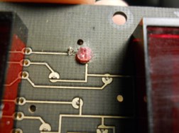
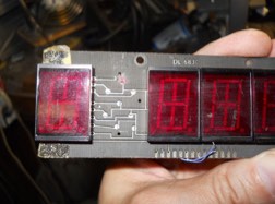
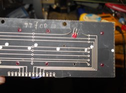
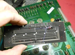
In a number of cases folks are missing one or more segments from their LED display and at this time there is no replacement (in progress though!) so for the meantime I thought I'd show how I restore bad LED displays with a series of photos:
(in progress)
| 
 Click here to order Parts


