Gottlieb Ground Cures by series: (updated
December 15, 2021
)
Symptoms these ground upgrades help fix: Overheating transistors, sound(s) cutting out, flash lamps melting ramps, solenoids overheating slowly, displays cutting out, pop bumpers being erratic or dead randomly, MPUs locking up at random. For the theory behind all this click this link
System 1 (1977 - 80: Cleopatra - Asteroid Annie)
System 80/A/B(1980 - 82: James Bond - Circus, (/A 1982 - 85: Devil's Dare - Ice Fever, (/B 1985 - 89: Big House - Bone Busters Inc.)
System 3 (1989 - 96: Lights-Camera-Action! - Barb Wire)
System 1 - VERIFY ALL GAME FUSES ARE CORRECT BEFORE PROCEEDING!!! |
 |
|
The ESSENTIAL ground modification if the game is working (or even if not), and you want to KEEP (or get it) working!
Symptoms of missing ground connection here and on the driver board (below) are overheated driver transistors - these lead to melted coils - and that the fuse doesn't blow until damage is done. |
 |
|
Recommended ground modification to System 1 regulator/power supply if you have to take it apart for service and want a nicer look than a wire soldered to the cap and jammed under a screw - this gives the same electrical results as the above mod. |
|
|
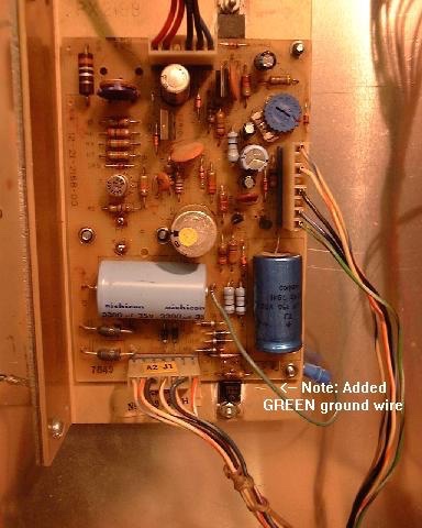
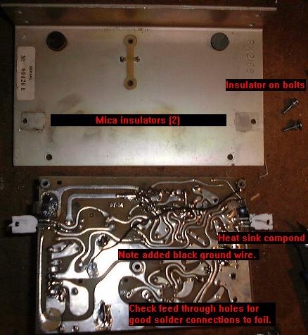
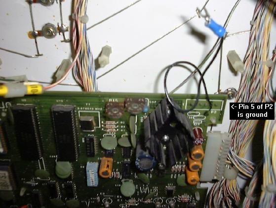
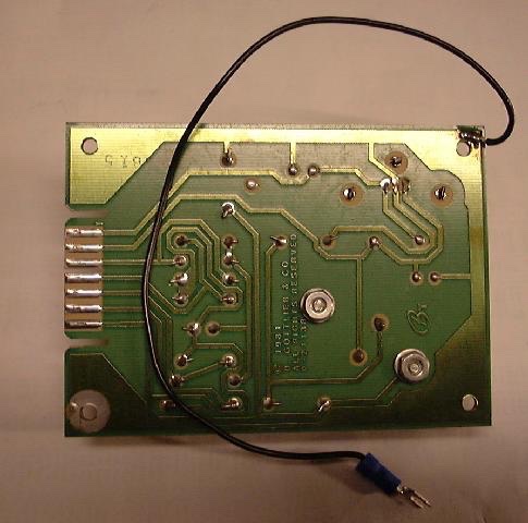
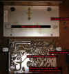
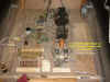
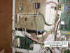
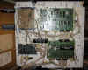
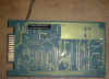
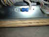
Please note that ALL Gottlieb Electronic pinballs have problems with the ground connections (back story here). This stems from their reluctance to learn from Williams, Bally and Stern's use of the metal mounting plate as a common ground plane for the game boards. Gottlieb System One pins had only a single ground pin going to the regulator supply, and this would weaken over time the same way as the System 80(X) problems are covered below. A simple cure for the System 1 and 80(X) regulator supply ground problems is to connect the ground plane of the regulator circuit board to one or two of the studs that the securing screws use to hold the circuit board to the regulator's heat sink, and then making sure that the heat sink frame is connected to the cabinet ground plane. All you need to do is add a wire from the (-) end of the large filter cap to the bolt on the underside of the frame - see the photo. If you have to take the supply apart for repairs then here is a picture of the mod done to a System 1 power supply (the BLACK wire), also note the fresh heat sink compound (silicon) on the both the outboard +60VDC regulator transistor and the -12VDC regulator.
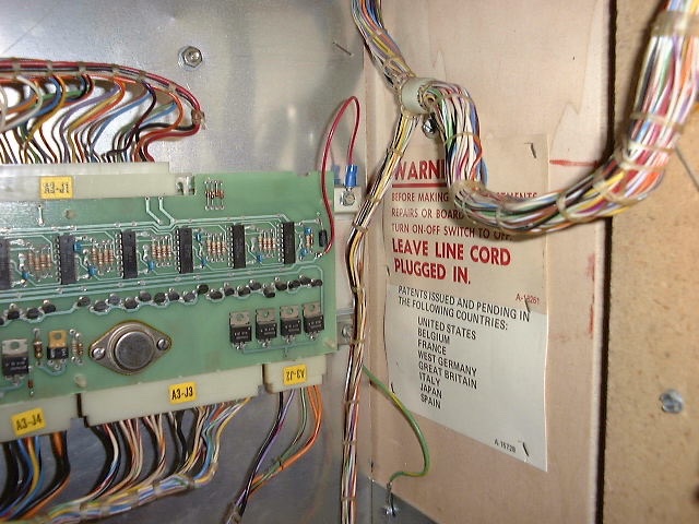
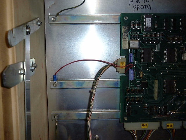
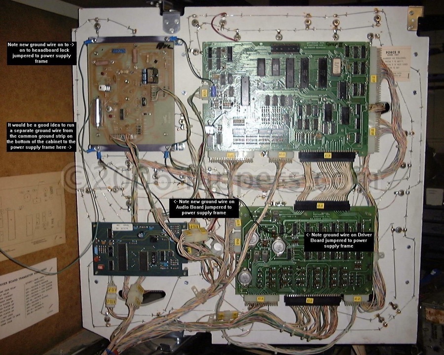
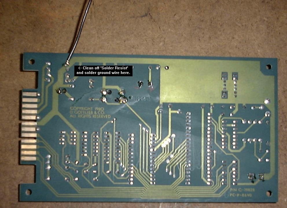
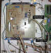
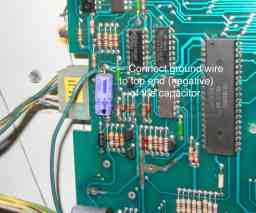
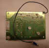
I now recommend the adding of ground wires from both the MPU and driver boards and screw them under a screw on the rear metal panel. (See the pictures on the left...) The ground wire on the MPU is best if soldered to the bottom of C16 . The ground wire from the driver board would be easiest if soldered to the bottom of C1. Now these two ground wires go to the grounded frame of the power supply. (updated Oct 1, 05)
>>>NEW<<< The System 1 Audio board uses a separate +5VDC regulator, and if it's bolts are loose there is the possibility of damage to the TTL circuits on that board. So tighten the bolts! In fact it would be best if you put star washers under both the bolt and nut to make a better ground connection between the case of the 5VDC regulator (LM309K) and the ground plane copper on the underside of the sound board. You might as well run a jumper from this ground to a good tie point along with all the others. |
| |
|
Coils still burning up? Here is a process for System 1 games (works with System 80 on with minor modifications).
You will now need a voltmeter and a couple of jumper wires.
1) Unplug the game.
2) One way to see if you can find the problem is to first remove the 28VDC solenoid fuse before doing the following tests (lets not burn up any more coils).
3) Turn voltmeter off(why waste the battery?) Connect one jumper wire to the copper ground plate on the transformer board under the cabinet. Connect the other end to the negative of the filter cap on the power supply and set the voltmeter to the 2VDC range.
4) Now turn the game on and leave it on for an hour or three.
5) (hour or so later) Now turn voltmeter on - the voltage should be pretty much 0.00VDC, with a max of 0.1VDC (less is better). Turn the meter to AC voltage, again should be virtually zero volts AC. If the DC voltage is over 0.01 find the problem! repeat steps 3 - 5, going on to 6 when 5 is OK.
6) OK, now the power supply common/ground voltage relative to the cabinet ground is essentially 0VDC - check the voltage from the driver board logic common/ground to the cabinet ground (that copper strip). This too should be virtually 0VDC - under 0.01 if ground wires added.
7) OK, turn game off and replace solenoid fuse. Put meter (turn on and set to 2VDC range) lead back to power supply capacitor common/ground (you did leave the other lead connected to the copper ground strip - right?). Watch meter when you turn on the power. Should be same results as step 5. If not turn game off and fix ground connection problem.
8) If step 7 is OK, then move meter lead to drive board common and compare to reading in step 6. If OK, then feel temperature of the driver transistors with your fingers (28VDC, should be fine if fingers not damp otherwise mild tingle) - should be at room temperature. Check with finger again in a minute or two. These should NEVER be much more than room temperature when the game is on but idle (attract mode only). If hot or warmer than neighbours turn game off and let us know - there are a few other tests you can do with a voltmeter and the solenoid fuse removed that will pinpoint the problem. |
System 80/A/B - VERIFY ALL GAME FUSES ARE CORRECT BEFORE PROCEEDING!!! |
 |
|
Symptoms of bad ground include: any displays on the playfield flicker or are dead, pop bumpers do not fire reliably, coils slowly overheat, transistors on the driver board cook the PCB underneath them.
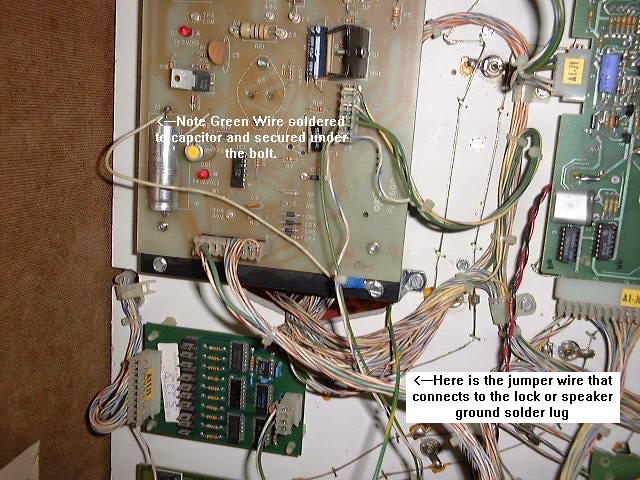
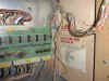
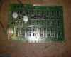
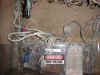
1st - check if the game still has this Orange capacitor - replace it if so, they are all bad! |
 |
|
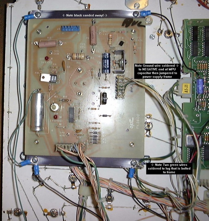
2) Next add a ground jumper wire from the capacitor on the Voltage Regulator board to it's frame- sand the black coating off the plate though. |
|
|
3) Next add a jumper wire from the MPU to the Regulator frame. Then jumper the two green wires on the side plug to the regulator to the frame (this will help with display flicker that sometimes occurs on games with the display in the aprong rather than in the head)
3a) The Pop bumper driver boards (PBDB) get their logic +5 and ground connections from the MPU - check the condition of A1J6 pin 9 (GND) and pin 18 (5V) on both the MPU board and the connector pins for signs of corrosion or flattening of the wiper pin. The ground connection for the pop bumper driver transistor goes through plug/socket A7J4 on their way directly to the ground strap in thebottom of the cabinet. |

|
|
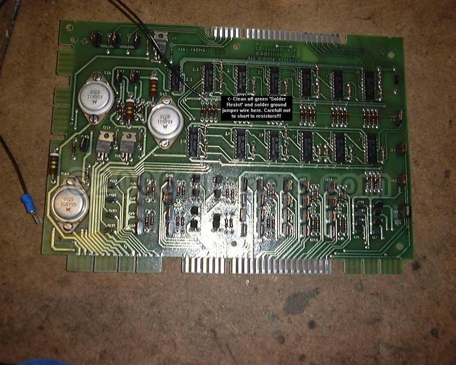
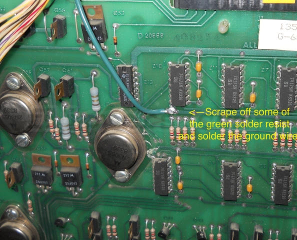
4) And of course it is ESSENTIAL to add this ground wire to the Lamp/Solenoid driver board - goes to the Regulator frame... |
 |
|
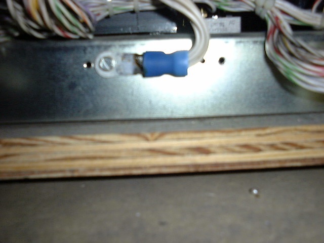
5) Lastly, (updated) Move the wire that goes to the lock to the regulator frame and then jumper connect it to the lock. or speaker frame, and for the best reliability it would be a great idea to run a separate ground wire to the copper metal strip that has all the wires soldered to it in the bottom of the cabinet just beside the transformers. See top picture in this section (Orange capacitor) |
 |
|
The remaining steps (6 - 9) are recommended, but no damage will result if not done.
6) Then flip over your small sound board (early System 80 games-Time Line, Spiderman...) and add that ground jumper (goes to frame of Regulator). |
 |
|
7) If you have the Sound/Speech board (Volcano, Mars, Black Hole,...) then it should help if you add this ground wire. Then do the next step down! |
 |
|
8) And this ground wire is then recommended on the regulator for the Sound/Speech board... |
 |
|
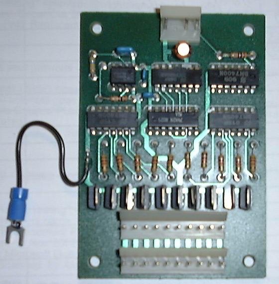
9) If you have a light chaser (Volcano, Mars, Black Hole,...) add a ground wire to it as well. |
System 3 (System 80B similar) - VERIFY ALL GAME FUSES ARE CORRECT BEFORE PROCEEDING!!! |
 |
|
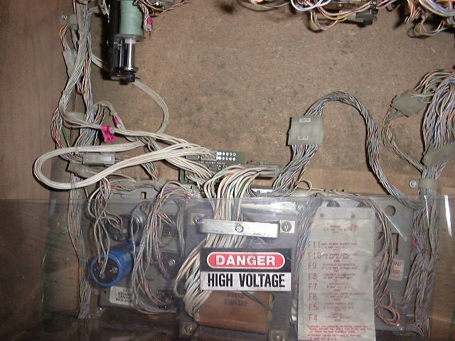
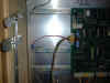
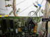
Find the power supply (under the playfield folks ;-) |
 |
|
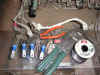
Tools etc...one source for the blue crimp lugs are Motormite #85443. |
 |
|
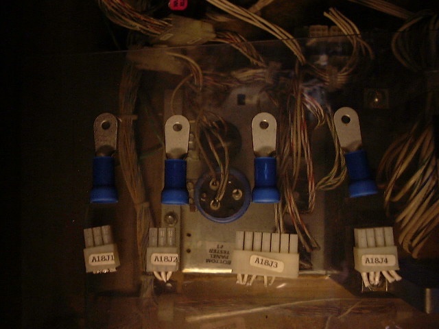
Replace these plugs with these crimp connectors |
 |
|
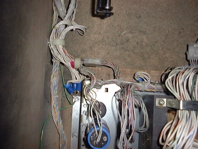
Strip wires for each plug and insert into crimp connector - you might want to solder the wires to the crimp connector (I do). |
 |
|
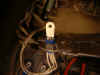
Secure the new connectors under a mounting bolt or... |
 |
|
Bolt directly to the metal transformer box. |
|
 Click here to order Parts