|
 Click here to order Parts
|
|||
| site search by freefind |
(If you don't see the Google Translate's "Select Language", then your browser is blocking google translate...so enable googleapis.com)
Updated
April 15, 2024 -->
Gottlieb System 1(MPU) pinballs-the early Electronic (digital) games
Design flaws in System 1 pinball games & solutions
1) Protecting the Switch Matrix
1a) Check the Switch Matrix for operation
2) Subject: Recommended Gottlieb System 1 modifications - Driver Board
3) Subject: Recommended Ground Upgrades!
4) Subject: Game is locked up at power-up
4a) Subject: Game puts ball into shooter, but then freezes up
5) Subject: Game cuts out at random, or won't start (you need a voltmeter here)
6) Subject: TECH: Recharge those displays!
7) Subject: Re: TECH: System 1 Pop Bumper Coil meltdown
8) Subject: Setting up SS Drop Target banks
9) Subject: Bookkeeping problems, good 5101.
10) Subject: Self Test procedure for System 1
11) Check if display transformer B-17921 has a fuse!
Typical Gottlieb System 1 game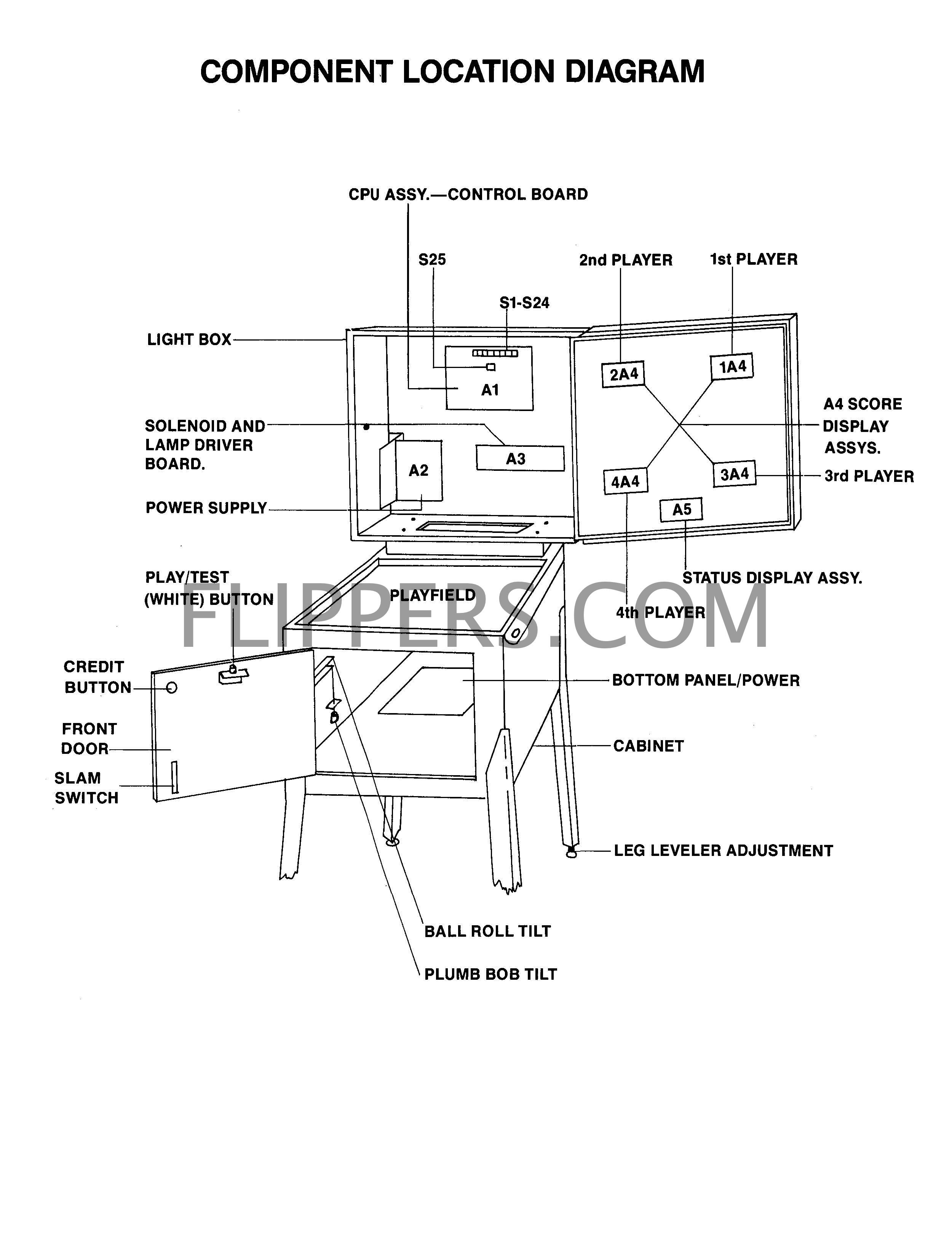
Cures for Gottlieb System 1 design faults.
There are four major problems with System 1 architecture.
A cure that we are testing is to prevent the over voltage getting to the irreplaceable IC U5 - A1752CF after either the switch drives or returns are hit with either a static electric shock or the 24VDC solenoid bus. The protection is simple, there needs to be clamping diodes inserted in the circuit. These can be placed across the resistors R65 - R72 with the band of the diode (1N4002 or higher) soldered to the +5VDC end of the resistor and the non-band end to the other side of the resistor. Then on Resistors R57 - R62, connect the non-banded end of the diodes (1N4002..) to the junction of the resistor and the trace leading to the IC and the banded end to a convenient +5VDC bus tie point.
The idea is that there are a pair of 1N4005 diodes on each input/output line, and the diodes are in series like this
(Common or Ground)---|>|---(input/output)---|>|---(+5VDC) .
The (+5VDC) is the +5 bus rail. The ---|>|--- is a diode. The (input/output) is EITHER the input or output line to be protected. This will prevent the input/output lines from going above the +5VDC line and thus protect the IC's from the 24VDC solenoid bus or the 6.3VAC light bus power.
If your MPU is corroded or dead we sell the replacement Ni-Wumpf MPU made in the USA - this will replace ANY System 1 games computer!
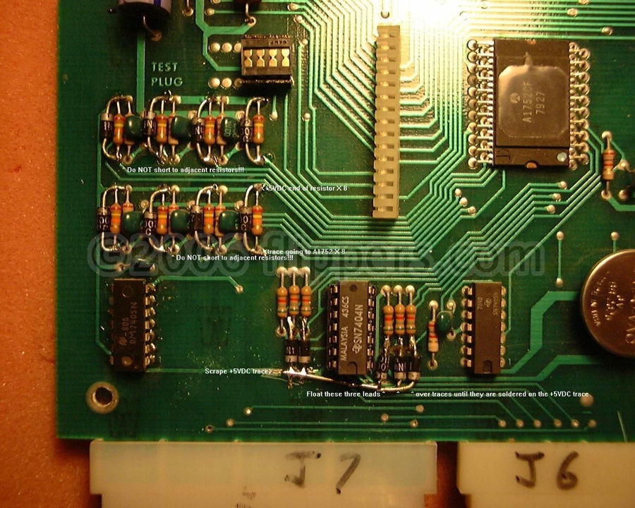 |
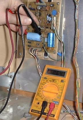
1) This picture shows my most recent (Jan, 2005) keep-it-simple experiment. This uses only 13 1N4002 (up to 1N4007 is fine) diodes installed to various resistors (Band End - Cathode - to +5VDC rail). Note that the 5 diodes beside the 7404 all tie to the +5VDC bus - the scraped fat trace at the lower left corner of the IC. The idea here is a simpler input protection. In this new (2005) case what will happen is the buffer IC (7404 or 7405) will self-destruct if too high a voltage is applied, BUT the valuable A1752(X) (made of Unobtanium) is not placed at risk. This is not as 7404/7405 IC friendly as my earlier design, however it is much easier for amateurs to install and provides ample protection for the A1752 to be installed in ALL Gottlieb System 1 games. Someday I'll make a plug-in board to avoid this, but I haven't sourced the edge connectors... 1a) An easy way to verify if the original System 1 computer is “seeing” a switch closure is to simply close the switch while watching the displays. Notice that tiny flicker when the contact closes or opens? That is the computer reading the switch to see if it is a coin, tilt, or start switch. This trick works as soon as the game powers up! I keep forgetting to add it to my tips on Flippers… In this case, if a switch is jammed closed, you can watch the display as you move the suspect. If you see a flicker then you know if the switch is active, and no flicker means either that switch - or another in a group of parallel switches like the 10 Points - is reading. ***Use NO metal adjuster or probe on the switches WHEN THE GAME IS TURNED ON otherwise you risk damaging or destroying the computer if you short the switch circuit to lamps or solenoid power!!!*** |
| 2) System 1 lamp/solenoid driver board design problems |
|
| The earlier run of Gottlieb driver boards (Cleopatra, Sinbad and early Joker Pokers) did not isolate the MPU board from the solenoid driver transistors with isolation diodes, and if a coil shorted out, this can cause serious damage to the MPU board. Making it somewhat expensive to service! Please check the picture on the lower left (here is a circuit diagram with the diodes) and see if you have these seven diodes on your board. The early boards can be updated by inserting diodes directly at the base of the driver transistors (picture #2), or traces were cut on the back and the diodes soldered in (picture #3). The recommended diodes would be 1N4002 to 1N4005 series, Do not use a 1N4001, at 50V it is not rated with a high enough breakdown voltage. We recommend that ALL Gottlieb System 1 game owners confirm this modification has been done, as even though the factory did this modification after the third or fourth pinball in that series, there is always the chance that you do NOT have a modified driver board due to a substitute repaired driver board some time in the past!
|
|
| Early System 1 Driver Board -NO isolation Diodes- | |
 |
|
| Later Revision Driver Board with 7 added Diodes (upper right and center bottom) |
|
| 3) The common/ground connection on the power supply...(updated December 12, 2005) |
|
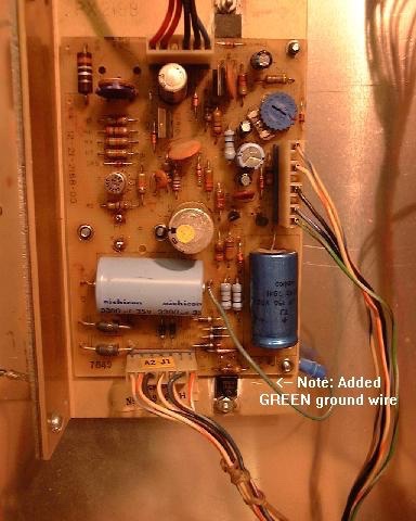
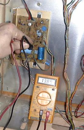
Added Ground Wire 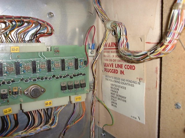 Driver board with added ground wire 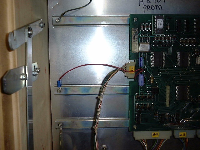 MPU with added ground wire |
Please note that ALL Gottlieb Electronic pinballs have problems with the common/ground connections. This stems from their apparent enability to learn from Williams, Bally and Stern's use of the metal shield as a ground plane for the game boards. Gottlieb System One pins had only a single ground pin going to the regulator supply, and this would weaken over time the same way as the System 80(X) problems are covered below. A simple cure for the System 1 and 80(X) regulator supply ground problems is to connect the ground plane of the regulator circuit board to one or two of the studs that the securing screws use to hold the circuit board to the regulator's heat sink, and then making sure that the heat sink frame is connected to the cabinet ground plane. All you need to do is add a wire from the (-) end of the large filter cap to the bolt on the underside of the frame - see the photo. If you have to take the supply apart for repairs then here is a picture of the mod done to a System 1 power supply (the BLACK wire), also note the fresh heat sink compound (silicon) on the both the outboard +60VDC regulator transistor and the -12VDC regulator. After re-assembly remember to use your ohm-meter to make sure that neither of the 2 transistors and/or the -12VDC regulator are shorted to the metal frame!! I highly recommend the adding of ground wires from both the MPU and driver boards and screw them under a screw on the rear metal panel. (See the pictures on the left...)The connection to the driver board is the bottom of the capacitor on the far right end of the board. The connection at the MPU is shown in the picture at left as soldered to one of the two capacitors C16 and C17. Either the bottom of C16 and the top of C17(a common junction on the underside of the board) - you can solder your common/ground jumper wire to either point. Double check that the green ground wire to the metal back plane in the headboard is firmly secured, if loose then this upgrade is not effective! It would be best to secure the common/ground jumpers to a single tie-point in the head. |
Chatting with a customer up in Yellowknife NWT (turn right at Alaska) about his Sinbad where the outhole had taken out his spider chip outhole driver and he asked if there was any reason he couldn't use one of the drop target bank resets to replace that signal and I agreed that there really wasn't a problem.
In fact it was a great idea!
If you jumper the burned out pin 8 of the A1753XX (U4) to U4 pin 1 (drives the main bank target reset) then the outhole will kick when the targets reset at the beginning of each ball!
Who cares if the outhole fires during the game when the bank resets? Nothing will happen as a result - no scoring, etc. - just an extra firing of an unused (at this moment) coil.
This should work for any System 1 game that has at least on drop target bank.
Don't forget to add the isolation diodes (#2 just above) - that caused the problem in the first place, usually because the ground upgrade (#3 just above) wasn't also done...
John :-#)#
4a) Game freezes up after ball is fired into shooter trough, flippers work, but no scoring and displays show steady zeros:
A bad GAME PROM (PERSONALITY PROM) still allows coining up and game start, but the machine freezes at that point. You see the GAME PROM holds all the switch, solenoid, and score tables in it, so if defective the game can’t score or do anything much other than kick the ball to the shooter trough…
One check if it is the game MPU (computer board - A1 or the PROM is to follow the game Self Test procedure (link). Does the Switch Test show correct numbers on the display for the switch pressed? Do the score displays cycle in their test? Do the game controlled solenoids fire: Outhole, Drop Target Bank, Game Over, Tilt, etc? If yes, but the game locks up as soon as the ball is shot into play, then the GAME PROM is your most likely suspect.
We sell licenced PROMs here on our Shopping Cart page (click to open new page).
5) Slam and Coin Switch issues:
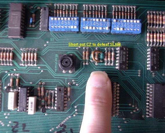 |
Typically you will turn the game on and the displays will come on IMMEDIATELY. No 5 second delay, no "Click-Click". You might well see the displays showing a wave like this O0O0O0 then 0O0O0O right to left flowing...we recommend that you disable the troublesome/useless SLAM circuit at the MPU board by shorting to ground the junction of R12 and C2. |
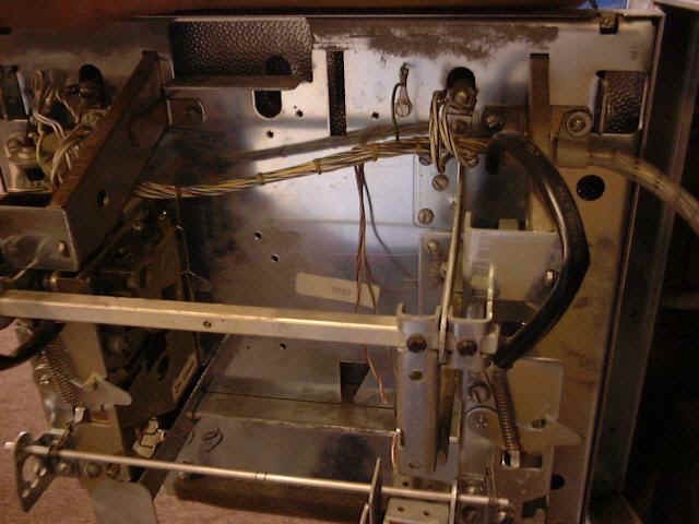 |
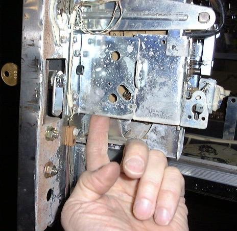
Another common cause of locked up games is when the coin lock-out wire is caught on a coin switch. First remove the coin mechanisms |
 |
Next look carefully at this picture and note the wire that is jammed into the switch blades, this must be pulled out gently and it will move back to it's normal position if not bent. |
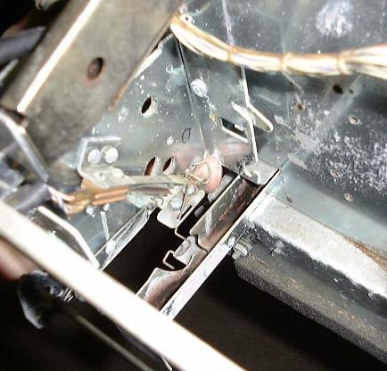
 |
Here is the lockout wire in it's normal position. |
 |
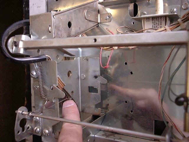
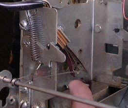
If you want to safely add free credits (without jamming the lockout wire...) on your game push up here... |
 |
You can just see the tip of my finger in this picture pushing up on the triangular piece of wire that activates the coin switch for a "Free" credit. |
Finally, please move the battery away from the MPU board. We recommend that you use two extension wires (red and black if possible) and have the battery lying on the bottom of the headboard (in a plastic bag) to protect against battery corrosion. For more info see our battery corrosion page.
Handy Service Tips for System 1 games
The following conditions represent unusual problems which have occurred and which, for the most
part, according to Gottlieb's service engineers, are easily prevented or solved.
Symptom: Game goes to "GAME OVER" during play for no apparent reason.
Solution: a) Check the two normally closed SLAM switches for adequate pressure.
Improperly adjusted switches will respond to game vibration levels and
produce this symptom.
b) Check the suppression diodes across the pop bumper(s), flipper and kicker
coil(s). An open diode or a broken solder connection can generate this
symptom (true for most brands of pinball games - jrr).
Symptom: While resetting the score levels stored in memory, holding the credit button in
fails to increment the score setting>
Solution: This problem and others which may occur while adjusting score levels can be
prevented by insuring that all drop targets are reset before attempting to
adjust the score levels.
Symptom: Game will register only one credit when coins are deposited and the book-
keeping memory appears to be blanked.
Solution: Power supply capacitor C2 (220pf) limits high frequency noise on the +5VDC
supply. If this capacitor opens, the bookkeeping functions will be inhibited.
6) Subject: TECH: Recharge those displays!
From: jacinth@umbc.edu (John Gantert)
Date: 11 Jul 1995 01:53:24 -0400
Organization: University of Maryland, Baltimore County
Message-ID: <3tt3kk$nnk@umbc8.umbc.edu>
Newsgroups: rec.games.pinball
(Here's a tip from a friend at the local auctions... Sorry I dont remember his name!)
Here's how to make your displays nice and bright again. (This tip specifically meant for Gottlieb 6-digit displays used on Sys 80 games, but it SHOULD work on any display).
Just attach 12vdc to the leftmost pin of the display, and attach the ground to the rightmost pin of the display. Leave it powered for 7-12 seconds (the vertical lines will glow red and become warm).
This should keep your displays nice and bright, and (I'm told) youwill have to repeat this about once a year.
-John
Note to recharge the 4-digit displays use only 8V maximum. (JR)
7) Subject: Re: TECH: Pop Bumper Coil MELTDOWN!!!
To: All
And another response to that age-old question...
>The question is: what happened? Any ideas? Is
>there something else I ought
>to be checking so this doesn't happen again? BTW:
>The pop bumper coils are
>"non-controlled" solenoids, so the MPU/Driver boards don't control the
>activation of the coil, just the "cup" switch on the bumper itself.
JND> Those non-controlled coils in the older games are the worst thing ever
JND> invented ... I had a Time Machine *burn* after it's
JND> non-controlled section
JND> on the CPU melted and then burned ... left a hole the
JND> size of a quarter in
Well, actually on this vintage of game Gottlieb had a direct control pop bumper. The cup switch had tungsten points and fired the coil all by themselves. The argument went that the computer controlled coils would not respond fast enough to the balls trying to tango between two tightly tuned pop bumpers, so let's have them bypass the cpu completely. Same idea occurred to Williams but they, as you mentioned, made a boo-boo by allowing the cpu to control the coils (who need that any ways??), which led to holes appearing in their solenoid driver boards when idiots over fused them.
If the pop bumper (back to the original question) cooks then you must check the condition of the contacts, you will probably find that they are pitted and this causes the contacts to momentarily 'weld together long enough to blow the coil. Replace the contacts when you replace the coil (get tungsten contacts) and set them so when you push on the bumper skirt on any point that the actuator pops back the middle with assurance. A little white lithium grease is sometimes in order in the cup.
:-#)#
8) Setting up EM/SS Drop Target banks
The correct way to setup a Gottlieb drop target bank is to (after repairing any broken/missing targets/parts) press the plunger of the lift arm all the way to the bottom of the, being careful NOT to press on the lift bar itself. You are pretending to be the coil you see, and thus only the plunger is pressed in. Now with the plunger bottomed out in the coil, loosen the coil bolts (four of them) enough that you can slide the coil up/down the slots, and slide the coil to the point where all the targets have raised enough to JUST pass the catch bar by about 1/32nd of an inch (1mm). Now tighten the four screws, and double check the adjustment by dropping the targets and pressing the plunger home. This adjustment, if done properly, will reset the targets every time, yet not break off the small stop tab at the very bottom of the targets. If those are broken off, the targets are being lifted too much. Pictures to come...
Here is some additional info on System 1 theory and some cures
9) Early System 1 MPUs bookkeeping problems
Found the following differences between early and later System 1 Gottleib MPUs - these changes affect how well the 5101 performs as battery backup memory and are recommended to do to your board if you have problems with setting replay levels:
Note you will need the manual for the moment to find these parts:
Near 5101 you want to check that R110, R113, R116 and R119 are all 2K7R (2.7K Ohms) NOT 27K ohms.
Near Z5 (74LS05) R150, R151, R152 and R153 - MUST be 12K NOT 24K ohms.
If you are still using a rechargeable battery check that R133 is 62R (62 ohms) not 58R. Not a big difference, but if the others are wrong you might as well do this one too.
Check that Q1 though Q6 are MPS-A70 - I seem to recall early boards may have used something else for Q1 through Q4...
(Work in progress...)
BOOKKEEPING FUNCTIONS AND SELF-TESTING SYSTEM 1 GAMES
The circuitry in these games helps the operator/owner perform many bookkeeping functions.
The information is shown one step at a time on the first player score display while the step number is shown in the credit display.
Pressing the button on the inside of the front door (the play/test button) begins the bookkeeping and advances it to the next step each time the button is pressed.
If the button is not pressed within sixty seconds of each step, the machine returns to normal playing condition.
The data in any bookkeeping step may be reset to zero while it is displayed by pressing Switch Button #25 on A1, the CPU control board in the lightbox/headboard. Then the play/test button must be pressed to enter the zero.
STEP INFORMATION
(Credit Display 0-13) - (First Player Display - Data)
0 - Total coins through #1 coin chute (left chute).
1 - Total coins through #2 coin chute.*
2 - Total plays.
3 - Total replays given.
4 - Number of times anti-cheat switches on front door and on ball-roll assembly have opened.
5 - Total extra balls.
6 - Number of tilts.
7 - First high score replay.
8 - Second high score replay.
9 - Third high score replay.
10 - Current "High Game to Date" score.
11 - Display test: All digits in first and third player displays step "0" through "9."**
12 - Display test: All digits in second and fourth player displays step "0" through "9."**
13 - Self-test: All CPU-controlled lights come on for five seconds. Each solenoid is energized one at a time. All closed switches noted by a code number in ball-in-play display.***
*If chutes are adjusted to be the same, coins deposited in either chute add only to the # 1 chute total.
**If button is not pressed within two 0-9 cycles, machine returns to normal playing condition.
***If no switches are activated within aone minute, machine returns to normal playing condition.
Adding Small Transformer (B-17921) Fuse in case the 69V display power supply shorts out:
The transformer board evolved a bit over the System 1 period. Primarily the factory added a line fuse for the smaller transformer that powered the displays as they kept burning out if the power supply failed.
Games that NEED this upgrade:
- Cleopatra
- Sinbad
- Joker Poker
- Close Encounters Of The Third Kind
- Dragon
- Charlies Angels
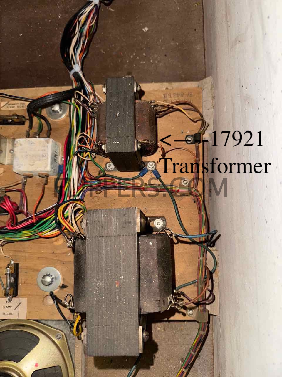
System 1 Transformer panel where B-17921 is located.
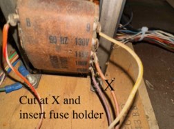
Cut wire to 120VAC and add inline fuse...
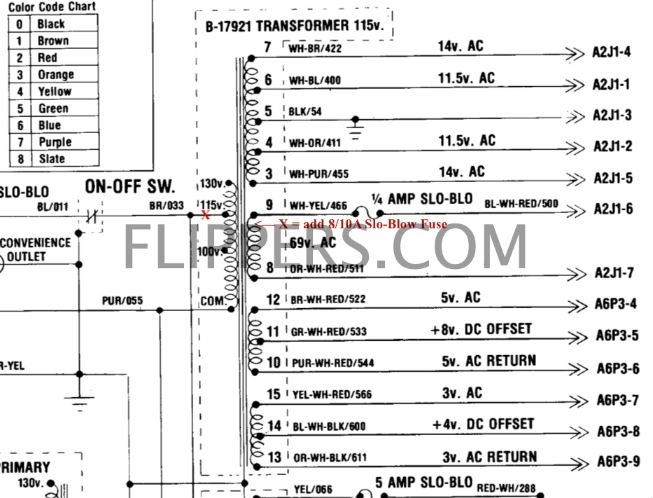
Schematics showing where the fuse is added

Schematics showing added fuse - note Gottlieb used 1A, I suggest 8/10A fuse.
Starting with Solar Ride, Count-Down, Pinball Pool, Totem, Genie, The Incredible Hulk,Buck Rogers, Roller Disco, Torch, and Asteroid Annie & The Aliens they all had the 1A Slo-Blow fuse added to the transformer.
(jrr-at-flippers-dot-com for those who do not have their browser set to open their email client) |